


Asus Crosshair II AM2+ Motherboard

Board layout & Features
Â
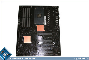
As with all of the Republic Of Gamers boards, Asus continue to make use of a Black PCB with blue, white and red slots. Maybe it’s just me, but I would like to see a shift in theme as the board at first glance looks much the same as the other ROG boards and while the theme is not unsightly and certainly not as badly coloured as some boards on the market today, it certainly would be nice to see a difference in your board from other ROG boards around.
Â
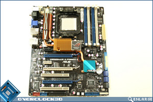
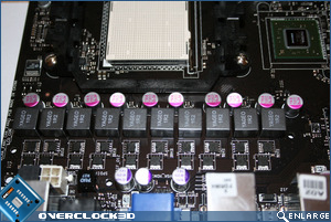
Apart from the obvious three PCIe x16 slots what does pop out at you is the massive cooler next to the CPU socket. Rather than surround the socket with Copper and thereby restricting the use of the CPU HSF size, Asus have put all their eggs in one basket. So what’s under there that requires so much cooling I hear you ask? Well I was as interested as you so I just had to have a peek:
Â
Â
Yup that’s a lot of Mosfets which deliver 10 phase power (or 8+2 phase as Asus declare) to your components ensuring that the voltages are cleaner with less ripple under load and more stable than ever before. With power delivery such as this the Crosshair is shaping up to be a monster overclocker.
Â
Â
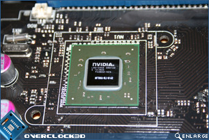
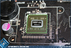
Connected via heatpipe to the mosfets is the new 780a (MCP) chipset and the nForce 200 chip. This chipset is heavily related to the Intel 780i but does have some significant differences. In contrast to the 780i, the 780a attaches all three SLI slots directly to the nForce 200 chip and then splits the bandwidth between them in a 16/8x/8x configuration. Therefore the 780a’s third slot is not crippled as in the 780i’s PCIe x1 slot which leaves the 780a a much more viable solution to Tri-SLI than its Intel based sibling.
Â
As reported earlier the 780a has an on-board GPU which, assuming you have a low end 8000 series card, can pair up and give your 3D applications a boost (Geforce boost) via the new Hybrid SLI, or could be used with 9000 series cards to save power by cutting power to your main 3D card and using the on-board GPU instead when 3D is not required via Hybrid Power.
Â
Â
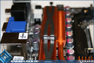
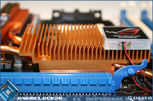
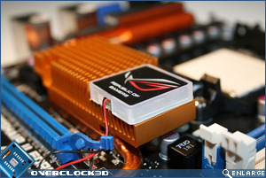
The main heatsink itself appears to be Copper coated aluminium and is emblazoned with ROG and Asus wherever you look. Asus have redesigned the fins themselves and advertise this as ‘Pin-Fin’ which in effect increases the surface area of the heatsink and while hardly revolutionary it is welcomed. I am however, puzzled as to why Asus take the time to install a new heatsink fin design and then partially cover it with a cosmetic emblem (which lights up white by the way and does look nice). It seems form is just as important as function with the Crosshair II. But I digress.
Â
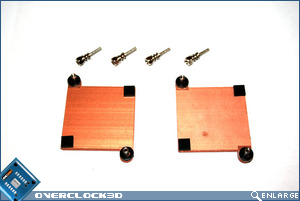
I applaud Asus in finally doing away with push pins to affix the 2 chipset heatsinks to the board. Instead they elected to use spring loaded screws with the Crosshair II. Push pins are still used in the mosfet area but this is sufficient for a solid mount. The screws are a godsend for those of us who wish to get a good, even and solid mount on the chipsets.
Â
Easy removal of the heatsink assembly is also a credit to Asus, as past boards have had a thick cement like TIM on the chipsets which never gave the best possible contact with the chips as well as making the heatsinks very difficult to remove. The Crosshair II however uses thermal tape on the mosfets and a thin sliver of thermal tape on both the 780a and NF200 chips which creates a much better thermal transfer and also allows easy removal should you wish to fit alternative blocks or indeed watercooling blocks. Asus have also gone one step further. Because the chipsets are held on by screws they have also added backplates to the motherboard for added strength and counter the added pressure on the chips thereby preventing damage.
Upon checking this particular board there didn’t appear to be any mounting issues and good contact was made throughout with the chipset. I should point out that removing the heatsink assembly will invalidate your warranty and as I have shown there is little need for you to do so anyway. So it’s all good in the power delivery, chipset and cooling department but what else has the board to offer?Â
Â
Â
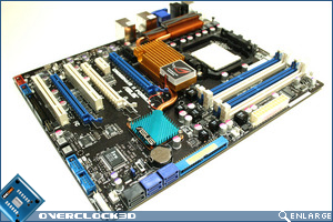
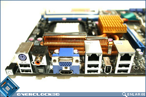
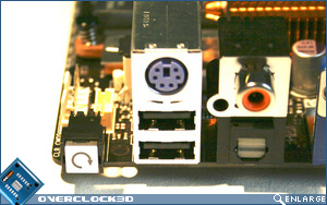
There is just about every conceivable connection you could wish for on the I/O backplate with the option for more 3 more USB hubs and an additional Firewire connection on board should you wish to use the provided adapter or require front panel connectivity. 2x PCIe x1 slots, 3x PCIe x16 slots and 2 traditional PCI slots provide the bulk of PCB connections and along with 6 SATA connections, 1x PATA as well as a floppy port should be all that even the most hardware endowed enthusiast requires. Perhaps of notable absence that you may have use for is the PS2 mouse port. Asus have finally abandoned the traditional port and now expect everyone to be using a USB mouse which is fair play as I fail to understand why anyone would use a PS2 mouse with a gamer orientated board such as the Crosshair II.
Â
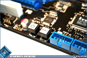
As with all ROG boards there is the usual and very useful onboard Power and Reset buttons which light up red and green respectively. This is a definite plus for those who prefer to benchmark their hardware outside of a case and therefore don’t have to rely on shorting the power pins to get the board to boot. While not exactly new as DFI have been doing this for some time now, it is a welcome addition and will hopefully be passed down to other boards in the Asus range and not limited exclusively to the ROG boards as it is an invaluable addition for system builders. You shouldn’t need to clear the CMOS due to the boards CPU parameter recall feature which will reboot to the last known good settings should your overclock fail for whatever reason. However this isn’t bullet proof and on the odd occasion that you do need to clear the CMOS Asus have made it very easy.
Â
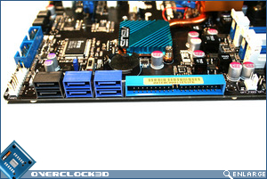
Situated on the I/O section of the board is another button, not dissimilar to the power and reset buttons allowing you to reset the CMOS from outside the case. Not only that but Asus have also included a fail-safe switch on the motherboard that should you switch from the default (enabled) position you can disable the Clear CMOS button and therefore prevent any accidental erasures when plugging in your peripherals.
Â
The 8-pin ATX socket is situated in the usual position for Asus boards, towards the top, which will prevent cabling from hindering your view of the onboard LED’s which Asus call ‘Voltminders’. These groups of three LEDs (Red, Yellow and Green) appear next to the CPU, Memory, Southbridge and BR chip and indicate the voltage level you have set: (Red = ‘Crazy’, Yellow=High and Green = Normal). I’m not sure of the usefulness of these as I should already be well aware of the ‘crazyness’ of my settings but it could act as a reminder should I have inadvertently set something too high in error.
Â
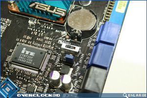
With solid capacitors decorating the board ensuring durability and 8 fan headers for supreme cooling it appears that Asus have thought of everything when designing this board.