


Aerocool V12XT 4-Channel Touch Panel Fan Controller


Operation and Testing
- First things first, this is a touch screen controller. Now we’re not quite at Star Trek levels of user interface compliance yet, and by that I mean we’re not able to control fan speeds with gestures of the hand over the screen. That said this unit is pretty easy to use and live with. As with most “touch screen” units, there are actually only specific areas of the screen that are sensitive and act essentially as interactive buttons. A rough representation of these areas can actually be seen in the image below.

- So quite a lot of interactive areas? That means quite a lot of options for interaction, which of course means quite a lot of control, and as we know, control=good.
- So what sort of control do we have? Let’s bring up an image of the screen whilst the unit is on to help us understand things a little better. The screen is separated into two areas. What I’ll call the rev counter area, which is the upper most section of the screen showing a visual representation of speeds (on the left) and temperatures (on the right). The second area is what i’ll call the main interactive area, which is located at the bottom of the screen. this is where we input most of the instructions and make requests for information.
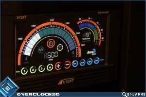
Pressing any of the yellow circles on the bottom row instantly informs us of the speed of the respective fan, whilst pressing any of the blue circles on the right gives information with regards to the temperature as read by the probes in the respective areas. It’s worth noting that these blue circles come pre programmed as, from left to right, CPU, VGA, HDD, SYS. So if you have your temperature probes positioned in those locations then all is well and good. If however you’ve got them positioned in other locations, e.g. top of cane and bottom of case, or intake and out-take, then you’re just going to have to remember what’s what.
We also use this lower section to program in the fan speeds and temperature alarms. Before changing anything it’s necessary to press the small padlock icon. The instructions tell us this is here to prevent unintended changes to settings, to be honest I found it a little unnecessary and annoying. Ok so we press the padlock, then we press the yellow circle for the fan we want to change then we press the numerical representation of the fan speed (in the image above it’s at 1500RPM) then we use the + and – buttons to alter the speed, then we press the pad lock again to secure the setting (or leave it alone for 30 seconds and it will lock itself. I’m sorry, but a process with so many stages hardly needs a padlock to unlock it at the beginning.
In drawing your eyes up to the padlock you’ve by now already noticed the rev counter area. As you’ve by now alrady worked out the left hand side of this area is a visual representation of the speed of your fans, or more specificall, the speed of the fan selected. If all your fans are set to the same speed, then of course this is representative of the group also. The right hand side shows a slightly smaller display this time with a representation of the temperatures for the respective areas your temperature probes are located.